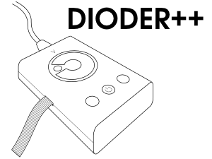
Programming a three-button DIODER
This is a tutorial describing how to hack the IKEA DIODER and how to make it more awesome by reprogramming the PIC and adding external interfaces.
Warning: It seems that IKEA has started selling a new version of the DIODER that is not compatible with this tutorial; see the section about device variants below.
Click on the image for a video introduction to the project.
Contents
Intro
DIODER is a series of LED stripes and controllers from IKEA, intended for bookcase lighting or similar, and it can be modified easily. Its core component is a PIC16F684, for programming which this article includes an introduction.
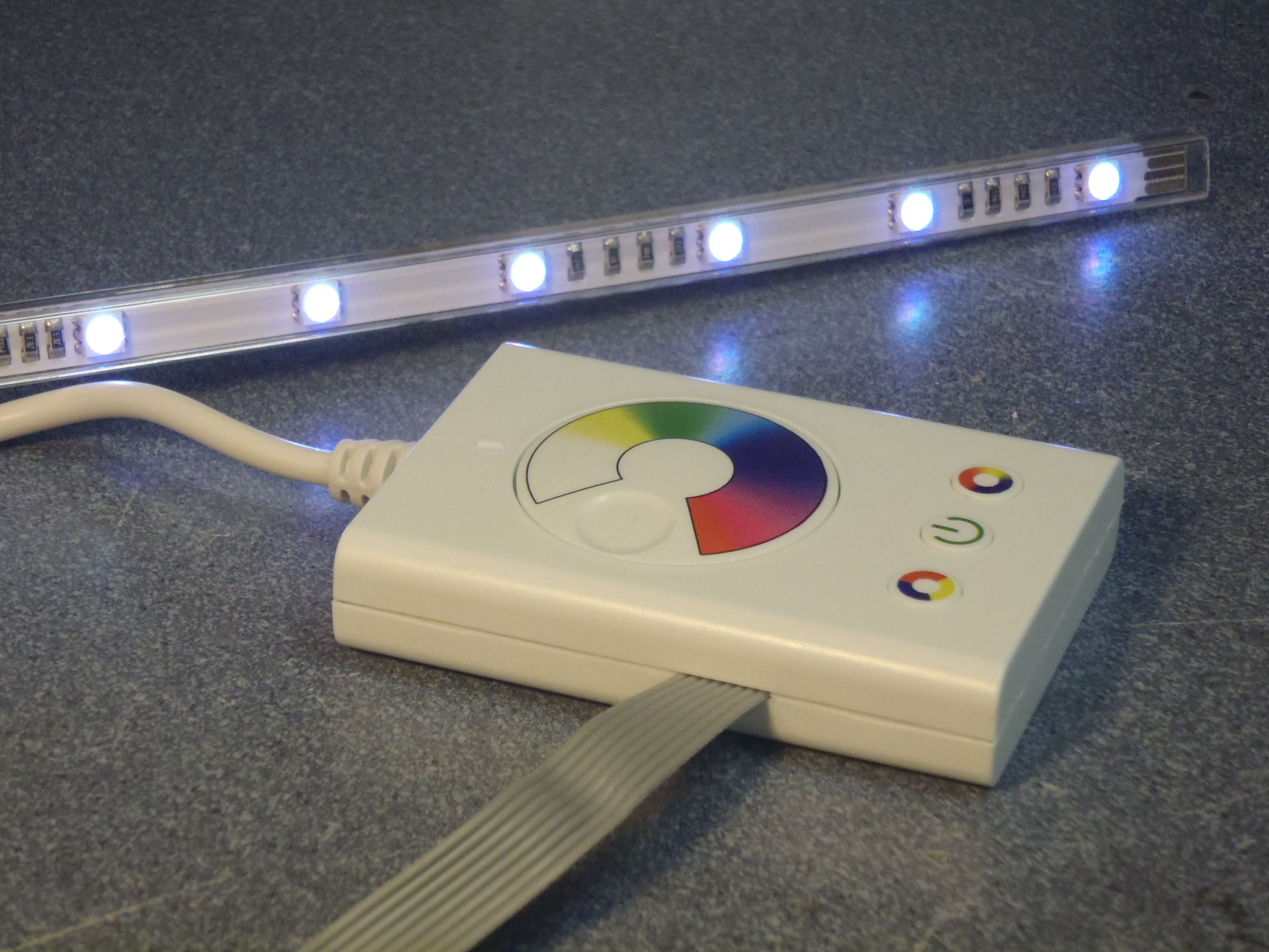
The particular variety this is all about is the RGB version of the DIODER that has a controller with three buttons and a color wheel (the one with four fixed stripes; this description should work for the version with flexible stripes or four disks as well). I bought mine for 30€.
I am aware there are pre-existing "DIODER hacks" (A "real" Ikea Dioder hack, Another IKEA DIODER HACK). Both of them replace the builtin PIC with another device, and they refer to a different controller version (the one with a single button).
In order to follow through the tutorial, you'll need:
- a DIODER
- a soldering station with some tin-solder
- 8 wires, preferably an 8-pin flat band cable
- a multimeter (recommended)
- a PICkit2 programmer
- a computer with
- sdcc (packaged in major Linux distributions; for further introduction see Micah Carrick's article)
- pk2cmd (Linux pk2cmd installation instructions)
Basic soldering and C knowledge are assumed.
Hardware description
Apart from cables and mounting equipment, the DIODER consists of three groups of devices:
- The hub: white plastic box to which the 12V 5W power adapter is hard-wired. Supplies the control device with power and routes its output to four sockets on the side.
- The control device: white plastic box with a color dial, a power button (central), a fade button (right), and a color change button (left). Connected to the hub with a 6-pin plug.
- Four led stripes: plastic cased circuit board stripes with 9 RGB LEDs each. Groups of 3 LEDs are in series, with current limiting resistors in place. The stripes can be connected to the hub with 4-pin plugs, or daisychanined from another powered stripe.
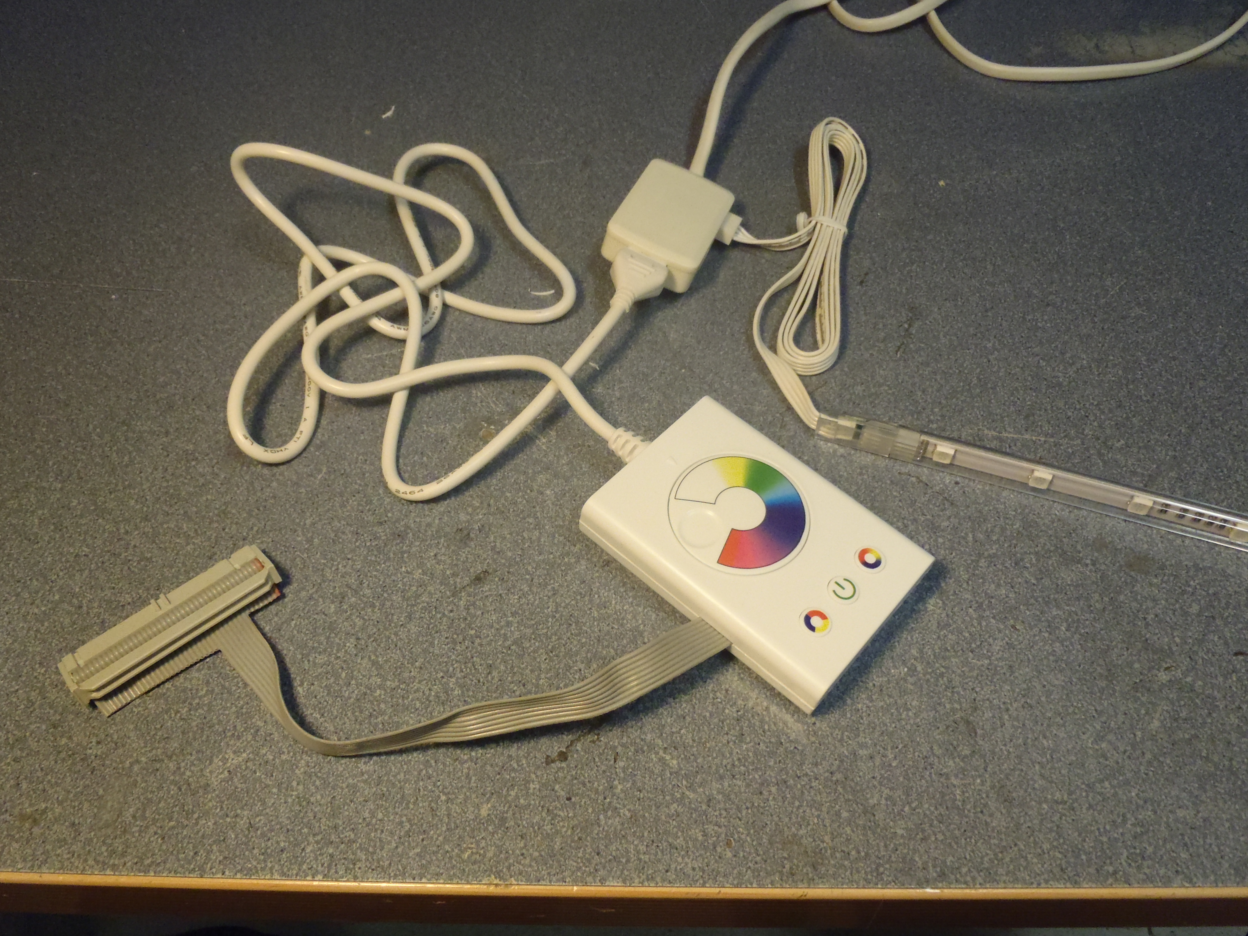
The hub has its power cord at the back, a LED stripe connected at the right side, and the controller at the front. The gray cable is an addition from this tutorial.
The control device
The control device is closed by a snapping mechanism, so some force has to be applied to open it. (Did I yet say this probably voids your warranty? No? Now here it is: Once you open that device, your warranty is void, and you're on your own; neither do I take any responsibility if it fails.)
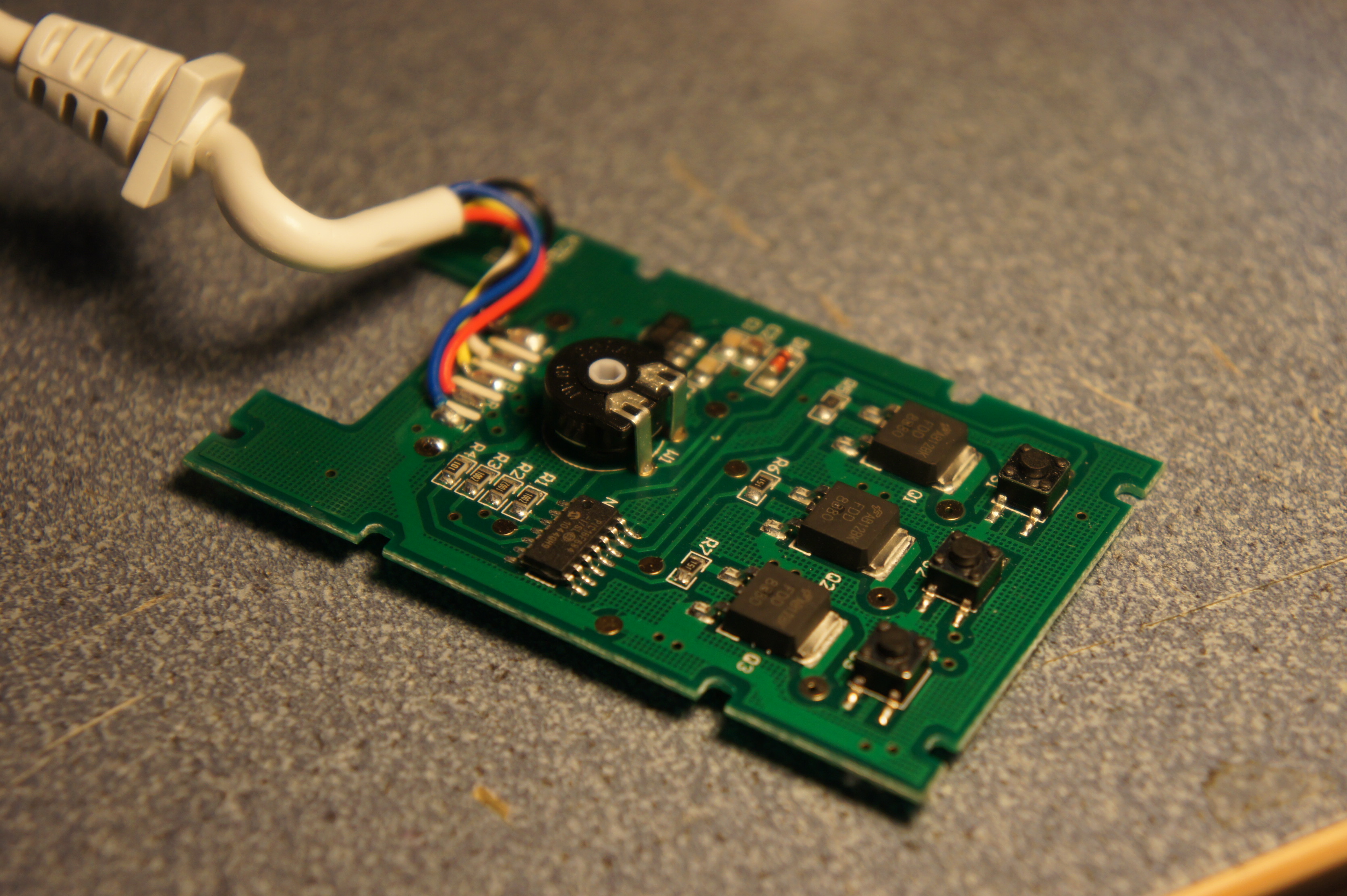
This is what the controller looks like when opened.
The internals are hardly surprising:
- a PIC16F684
- 3 push buttons S1/2/3 (with a pullup resistor R1/2/3 each)
- 3 FDD880 N channel MOSFETs Q1/2/3 (with a resistor R5/6/7 each between its gate and the PIC)
- a rotational voltage divider W1 (with another resistor R4 between its middle point and the PIC)
- a 78L05 linear voltage regulator N1 for powering the PIC with 5V, with a protection diode D1 and stabilising capacitors C1/2/3
- a 6-pin output connector
What's interesting here is the choice of FETs – they are rated about 10A current according to their FET data sheet (Figure 5). Given an appropriate power supply, they could probably drive much more than the four stripes of a set. The limiting part seems to be the power supply, which would have to be replaced by a larger one.
Pimping it
Soldering
The PIC16F684 can be programmed in-system -- no component involved breaks when putting the 12V programming voltage to it. (Programming voltage is connected to the power button, so don't push any buttons while programming!)

Top view of the controller, with the important solder pads marked.
All the pins required for programming (numbered counter-clockwise, starting at the corner with the notch:
- pin 1: operating voltage Vdd,
- pin 4: programming voltage Vpp,
- pin 12: programming clock ISPCLK,
- pin 13: programming data ISPDATA, and
- pin 14: ground Vss
) have large pads attached to them, where wires can be soldered on easily: Put the tip of the soldering iron on the pad and feed the tin to the pad for a brief moment -- some of it should melt and form a drop covering the whole or at least some area of the pad. Do the same with the wires (especially important if they are braid wire), then re-heat the drop on the pad while putting the wire on top of it; it should sink in and form a good connection.
Pins 8–10 (as well as pins 2 and 6, which I chose to leave unconnected as they are not that easily accessible) can be used for communication with the outside world, and are a bit harder to hit as they are not connected anywhere. Solder wires directly to the pins by covering the wires with tin and bringing them in contact with the ends of the pins while heating them. Be sure not to heat for too long, or you might fry the PIC.
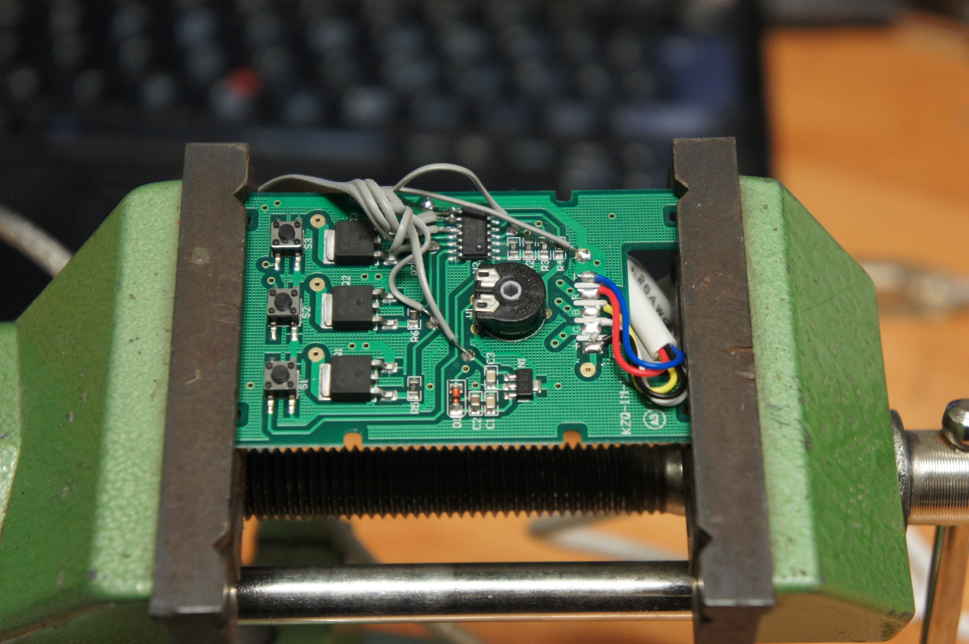
With all the wires soldered to the board, it could look like this.
CHECKPOINT
Configure your multimeter to connection tester mode ("beeping"), verify its operation by connecting the two probe ends (it should beep while they are connected), and check that each wire is connected to the respective PIC pin and that no two wires are connected.
Testing the programmer
For programming, I used a Microchip PICkit 2 programmer and the Linux version of their pk2cmd software (unfortunately, there seems not to be a free alternative, but at least it's gratis and they provide source code). Any other PIC programmer will do as well, but this is the one I had at hand. Other programmers will require different software.
Disconnect the DIODER from its power source and connect wires from the DIODER to your PICkit. The names on the "Top view of the controller" image above match the ones on the PICkit connector pinout.

The blue wires connect the PICkit with the plug at the end of the cable to the PIC.
As a first step on the computer side, read the configuration register [1]:
$ pk2cmd -PPIC16f684 -GC
Read successfully.

Configuration Memory

000C

Operation Succeeded
| [1] | The syntax used here is common for UNIX style systems -- lines starting with $ are what the user entered, successive lines are program output. On a Windows prompt, this would look like C:\> pk2cmd /PPIC16f684 /GC. |
This shows that the PIC really talks to us, and the PIC data sheet (register 12-1, p.100) tells us that the response means that fail-safe clock monitor, internal external switchover and brownout detection are disabled (the first 00); data memory and code protection are enabled, power-up timer and watchdog are enabled, and the oscillator selection is set to use the internal clock and keep the clock pins as GPIO pins (0C).
CHECKPOINT
The 000C Operation Succeeded indicates that the PICkit2 can talk to the PIC. If it fails with No PICkit 2 found, make sure the PICkit2 i connected to the computer and that you have sufficient privileges to access it (try sudo pk2cmd ...).
For all other errors, check the wiring; make sure the PICkit connector pinout (from the Linux pk2cmd installation instructions) and the connectors on the board (see the Top view of the controller image) match.
New software
It is now time to write a new firmware for the DIODER. A minimal example program consists of:
A platform specific header file inclusion: This is where expressions like PORTA come from that we'll use later.
#include "pic/pic16f684.h"
Configuration bits: These settings determine how the chip will behave and take effect before the rest of the program starts running, e.g. that we'll use an internal oscillator as a clock source. They correspond to the 000C we've read above, just in a form that is readable more easily.
typedef unsigned int config;
config at 0x2007 __CONFIG =
    _FCMEN_OFF &
    _IESO_OFF &
    _BOD_OFF &
    _CPD_OFF &
    _CP_OFF &
    _MCLRE_OFF &
    _PWRTE_ON &
    _WDT_OFF &
    _INTRC_OSC_NOCLKOUT;
Some definitions that make the rest of the program easier to read (in particular, these describe which pin is connected to which LED channel):
#define RED (1<<2)
#define GREEN (1<<0)
#define BLUE (1<<1)
A main function that handles initialization (configures the LED pins as output pins) and stays in an endless loop that configures colors according to whether the central button is just pressed or not:
void main(void)
{
        TRISA &=~ (RED | GREEN | BLUE);

        while (1) {
                if (PORTA & (1<<3))
                        PORTA = RED | GREEN;
                else
                        PORTA = BLUE;
        }
}
In order to burn a first new program on the PIC, download the complete file and compile it using
$ sdcc -mpic14 -p16f684 minimaldemo.c
You will find that, among other files, a minimaldemo.hex has been created. This file contains the compiled code and the configuration flags in hexadecimal notation. You can upload it to your DIODER now -- but be aware that this will irrevocably remove the original firmware, as it can't be backed up due to protection settings. If you want to go for it, run:
$ pk2cmd -PPIC16F684 -Fminimaldemo.hex -M
Unplug your programmer and power the DIODER -- it should be yellow unless the middle button is pressed, when it will be blue. Congratulations -- now you are in full control of your device.
CHECKPOINT
If it doesn't, you probably already got errors from pk2cmd. In that case, try the configuration register reading above again to make sure the connection is still good.
If you get errors like
Program Memory Errors

Address   Good     Bad
000000    000000   000084
this does not necessarily mean that your PIC is broken. Just try disconnecting the device for a minute and try again. Hints on why this happens are welcome.
A more complete example program is the hardware demo, which exposes all three buttons and the color dial. It requires a bit more setup calls for the analog/digital converter, and in order to get all buttons to work properly. It also implements PWM (pulse width modulation) dimming of the LEDs.
Based on this tutorial, there is a more advanced firmware hosted on GitLab, which tries to implement some of the suggestions below.
Happy hacking!
--chrysn
With two little cuts in the case, you can close the case again and still use the cable.
Appendices
Possibilities for further expansion
The three additional I/O pins are currently left unused. Possible uses are additional buttons (internal pullups are available, so the pins can just be pulled to ground), sensors (e.g. reed sensor for turning on a drawer's lighting when opened) or a remote control (using software SPI).
If you don't even want tiny cuts in the case, use short cable and a five-pin header to the pins required for programming; you can then leave the programming header inside the case and just upload new firmware.
For better strength of the soldering points, drilling through the board at the pads and soldering the wires through-hole should be possible. Ground and Vpp already have vias that can be used for that. I am not sure how bad the problems with exposed copper from the back side will be.
Some applications might want to use the 12V provided as well; there are both pads and vias available for soldering.
Begin able to individually address the LED stripes would be a nice add-on, but this would require abandoning most of the hardware provided.
There are pin-compatible ATTiny devices (e.g. the ATTiny44) that can be used as a drop-in replacement for the PIC if no PIC programmer is at hand and you are already familiar with the AVR series. It should be possible to de-solder the whole PIC and replace it with an AVR device. Programming can then be done from any other AVR device (e.g. an Arduino). The ATTiny could even directly connect to USB using the V-USB library.
The power button is connected to the reset pin, so you can either use it as a pure "power off" button or sacrifice in-system-programmability.
The FETs can power much longer LED stripes -- it would be necessary to replace the power supply, though.
Further resources
These websites could be helpful in this field, although they were not used in writing this (as they were discovered later):
- Burningsmell's PIC16F628 page: example programs for PICs with SDCC
- IKEA DIODER USB Mod: another DIODER hack, using the same 3-button version
- OSAA Skilt 2.0: a page on the same topic, but with superior firmware and some hardware additions
- Ambioder: an extension of this project by Gabriel-LG, which implements a UART based on the hardware described here
Device variants
As of December 2014, it seems that some devices sold are not compatible with this tutorial any more. Images of opened cases indicate that the design was reduced to a single-layer design, with less over-sized FETs and -- most importantly -- another microcontroller. The new chip is labelled SC91F729BM, which I think is produced by a company named SINCOM and exclusively documented in chinese, if at all. (The SC-series website shows similarly named chips with data sheets that indicate an 8051 architecture).
As the new board resembles the original one in its outline, the change is likely not to be visible from outside; hints on how to tell the revisions apart would be very much appreciated.
About this tutorial
© chrysn <chrysn@fsfe.org> 2011, published under the terms of CC-BY-SA.
Thanks to the people at Metalab for providing tools and tips.
The original URI for this document is http://christian.amsuess.com/tutorials/threebutton_dioder/. It is available as HTML or as reStructuredText.